On this page, you can find information about my forays into hardware-based projects such as Gadgeteer projects and modules, etc.
Videos:
If you’d like to see some of my video demos (similar to the one below), you can check out my Vimeo channel.
Builds: What’s cooking in the garage?
Here are the projects that I’m currently working on or have recently built…
Gadgeteer IR Commander and Kinect Copter
This project uses the IR LED Array module described below to allow a FEZ Spider Gadgeteer mainboard to control a Syma S107 Infrared remote control helicopter. In addition to using Joystick and Potentiometer modules for control of pitch, yaw, and throttle, the project includes an Ethernet module which, when connected, turns the Gadgeteer into an IR server, allowing the helicopter to be controlled over the network from either a Windows Phone or Kinect client. You can read more about the project here on the .NET Gadgeteer Showcase. A video demo of an earlier prototype is below:
IR LED Array module for .NET Gadgeteer
The first project for Devhammer’s Garage is a custom module for .NET Gadgeteer. The module is an IR (infrared) LED Array, and I’m using it to control an IR remote control helicopter, but you could use it for all kinds of stuff, including creating your own Gadgeteer-based universal remote control, home automation, and more.
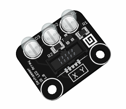
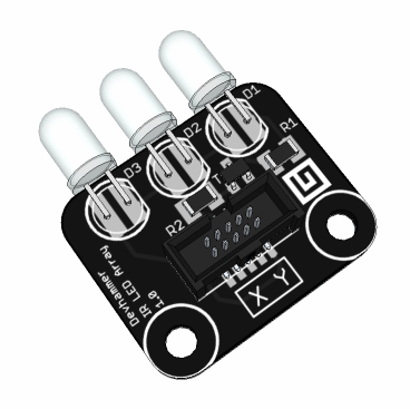
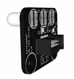
I’ve designed it so that the LEDs can be mounted in a variety of configurations, and I’m planning to give folks the option of which configuration they prefer, or possibly even providing the module as a kit that folks can assemble themselves. Here are a few renderings of what the module will look like when it’s done:
IR LED Array – Top mount
IR LED Array – Edge mount
IR LED Array – Bottom mount
At present, I’m in the process of ordering a set of PCBs to verify that the design works as expected, and have ordered all the parts needed to complete a handful of modules. If you think you’d be interested in having a module like this, please drop me a note and let me know.
The Gadgeteer driver for the module is available for download here.
UPDATE – 02/10/2012
The PCBs arrived today, and I’ve soldered up the first couple of modules. Everything seems to be working, though I’m making an adjustment to the IR LED configuration. In my original design, I had planned to use 2 wide-beam IR LEDs on the outside, in hopes of covering more area to the sides, with one narrow beam IR LED in the center, to cover more distance. In practice, it seems that the wide-beam IR LEDs don’t have quite as much oomph, so I’m switching the order and using 2 narrow beam IR LEDs on the outside, and one wide beam in the center. Here are a few more pictures of the first couple of modules that I’ve soldered:

|
| My very first module, and first surface-mount soldering job |
UPDATE 2 – 04/08/2014
While I’m still happy to happy to sell modules to anyone who’s interested, please be aware that these are sold as-is (whether assembled or as a kit) and do not have any support beyond the driver linked above. This is purely a hobby for me, and the only reason I charge at all is to offset my time in developing the module and help cover the parts cost. Just wanted to set clear expectations about what you’re getting.
IR Protocol Info
One of the things that presents a challenge when trying to control a device via IR is understanding the protocol by which the device is controlled. Most consumer IR devices use a 38khz carrier frequency (meaning that when the IR pulse is active, the IR LED(s) are not simply on, they’re actually flashing 38,000 times per second), which minimizes interference from ambient sources of IR light (such as sunlight). But the pattern with which this carrier frequency is switched on and off varies by device. For TV and audio remote controls, this is usually a simple short pattern, which is sent when a given button on the remote is pressed. This makes capturing and replaying these commands relatively easy, which is what a universal remote control with a learning mode does.
For devices such as the Syma S107g and similar helicopters, the controller sends an ongoing stream of packets, at a rate of several per second, that continually tell the helicopter what to do. This means that simply recording and replaying commands is not a very practical way of replicating the function of the controller.
The other option, then, is reverse engineering the protocol, which consists of finding a way to capture the signal (either by building an IR receiver circuit, or directly connecting an oscilloscope or logic analyzer to the appropriate output pins on the controller), and then moving the controls around and observing the impact on the signal.
The good news for me was that for the Syma S107g, this work was already done. I originally got my information from an RC forum, where a user by the handle of Darkstar2000 posted a thread in which he analyzed and shared his learnings on the protocol analysis (the interesting stuff for the Syma S107g starts on page 3 of the thread).
More recently, I’ve run across a few blog posts that cover the reverse engineering of the protocol, and I wanted to share those, since they’ll probably be helpful to anyone looking to R/E the protocol from another helicopter (or one of the MANY Syma S107g clones on the market, some of which do not use the usual Syma S107g protocol):
- Reverse Engineering the Syma S107G IR Protocol by Kerry D. Wong
- Reverse-Engineering a Syma 107 RC Helicopter by Jim Hung
- Reverse Engineering the Propel ExecuHeli IR Protocol by PetaVolt
Each of the above posts provides some additional insights that will be useful to anyone interested in the process of analyzing and replicating an IR protocol. Also highly recommended is the excellent IR Sensor tutorial over at adafruit, which has a ton of great background info on how IR sensors and emitters work.
The Hydrabot

UPDATE: I’ve postponed this build, since GHI was kind enough to create a great robot kit called the Cerbot. I’ll post some pics once I have my kit assembled, and maybe even a video…
The Hydrabot (so named for the fact that it’s powered by GHI‘s FEZ Hydra .NET Gadgeteer mainboard), is my first foray into from scratch robot building. Here’s the parts list (so far…I’ll add more parts as I put this thing together):
- FEZ Hydra microcontroller board
- Seeed Studio OLED Display Module
- 2x LEGO Mindstorms NXT Wheels
- 2x Tamiya 3mm Hexagonal Shaft Adapter for LEGO Wheels
- Tamiya Universal Plate Kit
- Tamiya Double Gearbox (includes motors)
So far, I’ve got the basic platform assembled, as shown in the picture above, and have tested both motors. Next up will be selecting and adding appropriate sensors (one sensor I have on hand that may be useful is the Seeed Compass module), a motor driver module, power, and then starting on the code to tell it how to drive. More photos, and video to come…